Updates…Again

Hi All!

I have yet to post content as mentioned in the last update. I have been really busy with projects and school work of late. However, I have been documenting my projects quite closely. I just need the time to digitize them.

Hence, I may not be able to make promises as to when content will be posted. But i will try my best to. Thank you!

Make.Share.Learn 

#startathon 2.0: Flood Protection Educational Model

20141012_130504 (2)

Introduction

We did this Flood Protection Educational Model as part of #startathon 2.0. You can check out the previous blog post on #startathon 2.0 here.

The name for this is a mouthful. But forgive us for that. We did not think that we needed to come up with a catchy name for it. As mentioned in the last post, we were too busy to take much pictures. I only took them when it was brought back to my house.

As the name suggests, our prototype aims to educate the public on flood protection methods or measures. The model will allow them to have a hands-on feel on how the various flood protection methods and also allow them to build and develop on their own flood protection methods. Communities in flood prone areas can adopt this to facilitate their flood education and also sharing between their people in regards to flood protection. By doing so, the people will be able to feel more empowered in protecting their own belongings in the event of floods and there will be less strain on the government or humanitarian aid.


Features

1. Flood Simulation

a. Water Reservoir

The Model is made up of two levels; the top level which has the house and the bottom level which serves as the water reservoir. A 12V water pump pumps water from the reservoir to the top level to simulate flooding. There is a plug on the top level which allows water to be drained back to the reservoir.

IMG_0582

Flood Protection Educational Model

IMG_0584

Water Pump

IMG_0582

Drainage Plug

b. Water Level Control

IMG_0585

Flood Simulation Control

We used an Arduino to control the flood simulation. When the start button is pressed, the Arduino will activate a relay which will allow the 12V water pump to be powered by the mini portable power supply(see here). Without using the external power supply and relay, the Arduino will not be able to power the pump with its 5V output.

A water level sensor detects whether the top level is flooded and stops the pump. The concept behind the water level sensor is simple; when there is no water between the two exposed wires (red and white), the circuit is open and the input pin on the Arduino is LOW. When there is water between the two exposed wires, the circuit is closed and the input pin on the Arduino is HIGH.

A transistor circuit is used to “amplify” the current between the exposed contacts. Without the transistor to amplify the current, the sensor may not trigger as there may be current loss between the two contacts. However, this also introduced another problem which was radio frequency interference. Radio frequencies generated current between the exposed contacts and triggered the transistors prematurely. This was solved then by cutting the wires short to limit the exposure to radio frequency. Thinking back I should have instead increased the resistance on the wires to make the base of the transistor less sensitive.

A stop button was added to stop the pump, even if the water is not filled up yet.

Lastly, LED indicators were added to indicate the status of the flood simulation; red meant that the operation was halted, yellow meant that the operation is ongoing and green meant that the operation is completed. This was also handy during troubleshooting, especially when the water level sensors were going off prematurely due to radio frequency interference.

c. Drainage Valve

IMG_0586

Reservoir Drainage Plug

We also had a drainage valve for the reservoir so that we could empty out the water and change the water if necessary. We got this valve from a urine bag.

2. Flood Protection Method Modules

The flood protection method modules were designed from existing flood protection methods. You can search them up to learn more.

a. Flood Wall Module

IMG_0583

Flood Walls

The flood wall module was made with 4 pieces of acrylic. The acrylic glue was not strong enough the and we had no time to redo it so we reinforced it with black electrical tape. The module is held in place with BluTack. It worked fairly well.

b. Sandbag Module

IMG_0583

Sandbag Wall Module

The sandbag wall module is made up of acrylic pieces glued and stacked together. It is stacked in such a way that it overlaps to demonstrate the method of sandbag stacking. This module prevents water from seeping through the gap it is blocking quite well.

c. Collapsible Walls

The four walls of the house are designed to be removed. This is so that we can simulate that in the event of a strong and sudden flood, the walls will collapse and reducing the surface area of the house that is exposed to the water such that the whole house is not swept away. Supporting structures such as pillar will still remain, along with the upper levels. People can then seek safety from the floods on the top level or the roof.


Conclusion

The flood protection educational model, though simple in design and concept, was still a challenging build for us. It took us almost 24 hours to build. Personally, I felt that the lesson to be learnt from this was to identify the key component in a project and place priority and emphasis to have it completed.

It was fun to challenge ourselves to create a solution for something new to us such as flood education and also work within this 26 hour time constraint.

If you have any questions regarding the Flood Protection Education Model, feel free to leave a comment or drop us an email.

And as always,

Make. Share. Learn 

#startathon 2.0: Team CUB3

IMG_0574

Introduction

Three of us attended a hardware hackathon called #startathon 2.0 and found it a very enriching experience. Hence, I would like to share with you more about the event and our experience during the event.

I do not have much pictures of the event since we were too busy during the event to take much pictures.


About #startathon 2.0

#startathon 2.0 is a hardware hackathon organised by ideasinc, Nanyang Technological University. It was held on 11 October 2014, 10:00am and lasted until the next day on 12 October 2014, 12.00pm at *SCAPE. Besides being a competition, there were classes conducted and consultations during the event.

Before #startathon 2.0

Even before the competition, there were 2 workshops, #startbuilding and #startideating, held leading up to #startathon 2.0. #startbuilding was a workshop on the Arduino, Sparkcore and MIT App Inventor while #startideating was a workshop on the themes for the competition and tools to understand problem statements and generate ideas for solutions.

#startbuilding was held at the National Design Centre. During #startbuilding, participants were split into 3 groups to learn the various tools(Arduino, Sparkcore and MIT App Inventor). Groups were rotated every 2 hours. I felt that #startbuilding was excellent. Lessons taught were useful and simple enough for anyone to pick up. For example, in the Arduino class, instead of teaching coding which would require a lot of time and would be too difficult for many who do not have any prior experience with programming, the instructors structured the lesson in such a way that it was about hooking up various hardware components and manipulating them with the codes available in the Examples provided with the Arduino IDE. After the event, the organizers sent us links to Github for getting the resources used during #startbuilding.

#startideating was held at HubQuarters@Level 4, *SCAPE. The themes for the competition were introduced to us there. The themes were Sparking Human Connections, Humanitarian Aid Re-imagined and Aging Fabulously. After the introduction of the themes, we were taught some tools to generate solutions from problem statements derived from the theme. One such tool was a table to generate ideas based on the technology available and Target Groups.

After generating solutions, we were taught about the Theory of Change. Theory of Change helps develop a coherent and plausible theory of how a product or service can ultimately result in your desired impact for the target group. It defines long-term goals and then maps backwards to identify necessary preconditions. You can find the slides for the Theory of Change used during #startideating here.

 #startathon 2.0

Participants were issued name tags and shirts during registration. There were different shirt colours(red, black and yellow) representing the different expertise(coders, makers and business) of each individual. I can’t recall which colour represents which exactly though. Once everyone had settled down, the organizers orientated us on the area and the proceedings for the event. As some of the participants did not attend the prior workshops, the organizers conducted an ideation session with them while allowing those who did their ideation to proceed with developing their ideas and setting up.

IMG_0578

Team CUB3: Flood Simulation Model

IMG_0577

Our work area

During the event, the organizers stopped the teams and shared lessons on managing our projects. They shared with us about Scrum. Scrum is an iterative and incremental agile software development framework for managing product development. We broke down our product into Minimum Viable Products(MVP), the minimum prototype to meet the consumer’s expectations, and identified processes to achieve the MVP. We wrote each MVP down on a post it note and placed it on a chart. This chart had sections divided by progress status. We would constantly update each process status throughout. This helped us apply our time effectively and keep track of progress when we got tired. You can find out more about scrum here.

There were consultants during the #startathon 2.0 which we could approach and get help. The consultants were very knowledgable and helpful. We would not have completed our product well if it were not for the consultants advice. Masterclasses on various skills and topics were also conducted by the consultants to equip participants with the knowledge they would require to build their product.

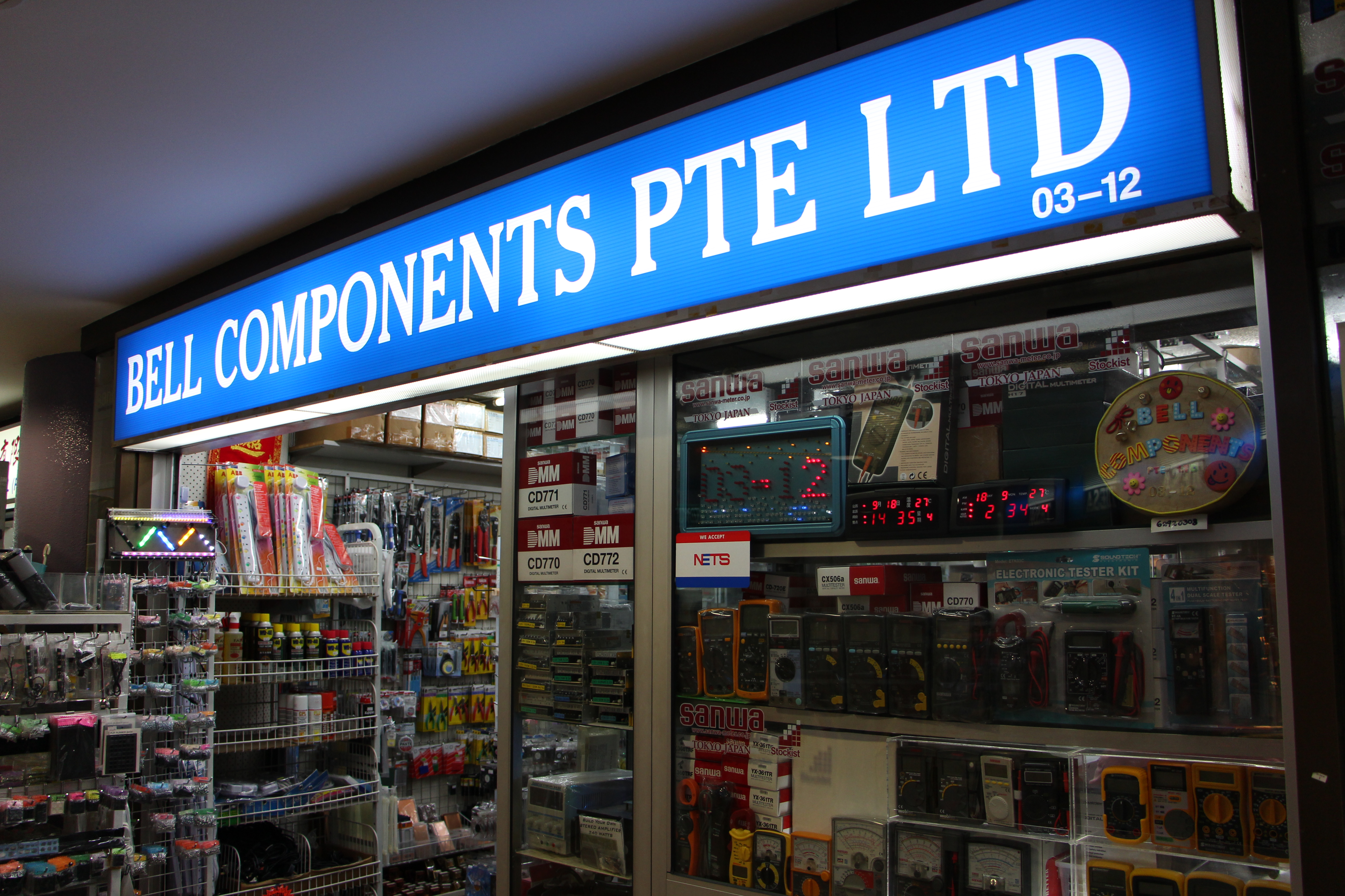
Tools and equipment were set up on the stage for participants to use. Arduino, Grove and Sparkcore Kits were made available for rental for teams. The fee for rental would be returned to participants at the end of the event upon return of the sets. There was also a pop-up store for teams to buy certain specialty item or components they may need to make their product. The organizers also arranged for a shopping trip to Sim Lim Tower for teams to purchase other components that were not offered during the event.

Meals were provided and came in buffet style. Snacks and drinks were available for participants throughout the event too.

As we were closing in on the deadline for the completion of our product, fatigue started to set in. Progress was slow and further deterred by setbacks. One main setback was sealing of the custom acrylic case. It was a time-consuming process to start with and was made worse with occasional cracking in the sealant and poor joints.

At about 7 or 8am, the organisers called for a Counter Proposal session to be held. During this Counter Proposal session, teams will give a 3 min presentation to other teams working on the same theme and have them critique their product. The presenting team cannot answer or rebut any question or critique given. This was done so as to identify points which were lacking in the presentation, which I felt was a very interesting and effective method. The critiques given to us were very constructive. In this session, it was pointed out to our group from the facilitator was that it was important for us to deliver the key function and idea in a fast and concise manner. For example, we would have to emphasize more on how the flood simulation model is a teaching tool in helping people have a hands-on feel on flood protection methods.

finalist!!

Finalists!

20141012_130504 (2)

Team CUB3

After a bit of tweaking, we managed to complete the product and took a short nap to refresh ourselves for the presentation. Teams had to submit their products for quarantine at 10 am. In the preliminary judging, teams have to present to judges and teams working on the same theme. We felt that our presentation was not very good.

Surprisingly, we managed to make it among the Top 7 finalists for the next round of presentation. We did not feel that we would have made it that far. Unlike the preliminary presentation, the finalist presentation was done on the stage and this made it hard for us to show and demonstrate our product as it was too far from the audience. We did not have much time to adjust or improve our presentation(we did not expect to make it that far!). You can check out our finalist presentation here.


Conclusion

#startathon 2.0 was not only a very fun and challenging and fun competition, it was also a very educational one with the various masterclasses and lessons conducted. Joining #startathon 2.0 was also easy on the wallet and close to free! The organisers were very knowledgable and professional in the execution of the event. I would recommend this event to anyone interested in learning how to make their idea into a product, coders, makers or entrepreneurs. Even if you are unable to find a team to register with, you could always join a team there or form one there.

Keep a look out for similar events and do not feel afraid or discouraged to join in. It opens up to greater learning opportunities.

I will share more about the Flood Simulation Model in another post so do look out for that. You can check out our Flood Protection Educational Model here. I will also try to update this post with examples and charts of the ideation techniques taught.

You can also have a look at the other projects from #startathon 2.0 here.

And as always,

Make. Share. Learn 


Update!

Hi! It has been a long time since I last posted something here. I was busy with some stuff. However, I am glad to let you all know that we will have a good line-up of posts within these two weeks. Do look forward to it!

Make.Share.Learn

DIY Project: Mini Portable Power Supply

IMG_0412

Mini Portable Power Supply

Introduction

Hi! I will be sharing with you the specifications and features of the mini portable power supply which i have recently put together. Quite some lessons were learnt as previously mentioned in the previous post.

I did this project to make myself a portable power supply I could bring around to test certain broken equipment which requires fixing. It is handy to be able to bring around a variable power supply such as this than to look for a suitable battery to power it up. I did some research online and found this method suitable.

This will not be a how-to-do post. To be honest, I was not quite satisfied with this as I feel that it could be better, especially for something like a power supply. I will cover some of the shortcomings in this post. Once I am finished with a more robust design, I will put up a how-to-do post.


Features

1.  Small Form Function

The size of this power supply is 13.5cm x 7cm x 4.1cm (L x Bx H). The sockets are positioned at the sides of the enclosure to keep the profile slimmer and so that a carrying case can be easily made for it.

The power supply can be split into 3 parts:

IMG_0390

The main body

IMG_0415

Output Cables

IMG_0384

Power Adaptor

This makes the power supply more portable. Different power adaptors can be also used on the main body. I could even use a battery to power the power supply.Here is what the insides look like:

IMG_0405

The insides

2. Variable Voltage

IMG_0400 IMG_0402

The power supply is made using a LM2596S Mini DC-DC Voltage Stabilizer/Regulator Module. It featured a small potentiometer for voltage adjustment. I removed the small potentiometer and replaced it with a larger potentiometer so that it will be easier for me to adjust by using my hands. I also bought a shiny knob from Sim Lim Tower for this.

3. Output Terminals

IMG_0391

Side View of the Main Body: Potentiometer and Output Terminals

I bought these banana sockets from Sim Lim Tower for about $0.80 per piece. They also sold better ones for $2.50 per piece but I felt that the $0.80 ones were good enough. These banana sockets not only allows me to connect to components using the banana cables(banana plug on one end and crocodile clips on the other) that I also made.


Shortcomings

1. No current adjustment

I was unable to find a voltage stabilizer/regulator module which allowed me to adjust the current as well. Without this, I may not be able to power some devices or equipment as the current may be too high or low. I will have to measure the current using my multimeter before attaching the power supply.

2. Inaccurate current measurement

When I connected the ammeter during tests, it gave out the wrong reading as compared to my multimeter. Hence, I decided not to connect it when assembling.

3. Sensitive Potentiometer

The potentiometer used was too sensitive. A small turn on the knob changed the voltage a lot. This is because the potentiometer could only be adjusted from 0 degrees to about 280 degrees for 0 Volts to about 15.1 Volts. This means that a small 10 degree turn would cause a 0.5 Volt change.

In my next attempt at making the power supply, I will choose a less sensitive potentiometers which will require more turns of the knob to change the voltage to allow for finer tuning.


Conclusion

It was a fun and useful project. It still has much more room for improvement and potential. I will continue to work on this. Do look out for the final design!

Feel free to comment on this project. I think that there is a lot more that can be done and if you have any ideas to improve this, I would be happy to listen. If you have any questions regarding this project, you can also leave it as a question in the comments or send it to me via email at make.share.learn@outlook.com.

Till next time,

Make.Share.Learn

Experience: Where I get my stuff

IMG_0338

What I bought recently

Hi there! Today I would like to share with you all on some of my favourite places to get materials and parts in Singapore. All of which are in the Bugis area. Sometimes I go there to buy specific parts and materials I require for projects, other times I just go there to see whats new or what can be used or fun to do. Without further ado, lets get started!


1. ArtFriend @ Bras Besah Complex

IMG_0276

ArtFriend

Truly a friend of the arts, ArtFriend is truly stocked with lots of art and handicraft items. I used to come here for acrylic sheets but have since found a better place, DAMA Trading Pte Ltd, to get it. But ArtFriend is still a place I turn to when I am looking for something that I cannot usually find in other places. Things such as a 28 Gauge steel wire for me to clear the 3D printer extruder of clogs, foam, acrylic and metal tubes. I sometimes go there just to find ideas by being intrigued by the stuff they sell. However, one has to be wary of the price. Acrylic for example was 2x more expensive than from DAMA.

ArtFriend is truly worth the trip there. Fantastic range of Art and DIY products to let you find what you would want and also let you discover new ideas.

2.  Sim Lim Tower

IMG_0303

Sim Lim Tower

a. SPACE Electronics (01-01A)

IMG_0277

SPACE Electronics

This is the first shop you see when entering Sim Lim Tower. It has a great range of items; From components such as switches and sockets, to stuff like CCTV cameras and TV antennas. They have another two outlets nearby. One is at Sim Lim Tower Basement 1 while the other is in Sim Lim Square(across the street). They carry most of the stuff I need, but do not carry certain items I would also need such as heat sinks, servo connectors etc. What I like about SPACE Electronics would be their Operating Hours. I can’t remember exactly when they open and close but they open on Sundays too. Most shops here do not open on Sundays. This is great for people like me who are sometimes busy on weekdays and Saturdays.

b. BELL Components (03-12)

IMG_0281

BELL Components

IMG_0282

Assortment of screws available here

BELL Components have a wide range of small electronic parts and a wide range of screws, nuts, washers, etc. This is where I would buy my screws and some small electronic components. What I like here is that they sell the screws and nuts in a bundle. It is easy for me to just buy a pack so that I can stock up my supply at home. You can also opt to buy it per piece.

c. HAMILTON (03-49)

IMG_0291

HAMILTON

HAMILTON is where i like to buy my thicker wires. Other shops carry the same gauge of wires but with a lower strand count. This was perfect for my quadcopter. I also like to buy jumper cables and cable plugs from here. The elderly Auntie and Uncle here are super friendly. It is a small shop.

d. SUN LIGHT Electronics (03-09)

IMG_0280

SUN LIGHT Electronics

When you go up via the escalator to the 3rd floor, SUN LIGHT Electronics is the first shop you will see. They have a great range of items and small tools as well. What is interesting here is that they also sell Arduino, Raspberry Pi, BeagleBoard, etc. I would not encourage anyone to buy it from here since they will mark up the price. Try getting your Arduinos or Raspberry Pis online on sites like element14 for a cheaper price. You will also be able to find robotics components here such as robot chassis, sensors, motors, etc. They even recently got into selling Go Pro, which surprised me.

e. SILICON Electronics (03-02)

IMG_0297

SILICON Electronics

SILICON Electronics is where I get my servo plugs and other connectors. They definitely have a great range of plugs and connectors. What you see is just half the store. Opposite this store is another store they own to stock the rest of their stuff.

 f. CONTINENTAL Electronic Enterprise (B1-25)

IMG_0299

CONTINENTAL Electronic Enterprise

Located at Basement 1, CONTINENTAL Electronic Enterprise has a great selection of parts and components. But what sets it apart from the rest is that it sells mechanical parts such as gears(even rack and pinion, worm gears, pulleys, etc), mounting plates, sensors etc. The uncle and aunties there are knowledgeable and friendly too. They sometimes open on Sundays(I can’t remember if it is the first or second Sunday of the month).

3. Ramen Keisuke Tonkotsu Four Seasons

IMG_0315

Ramen Keisuke Tonkotsu Four Seasons

Ramen Keisuke Tokotsu Four Seasons is located at Bugis Village, between Bugis MRT and Sim Lim Tower. I usually get my fix of ramen here. They offers 5 varieties of tonkotsu broth ramen; Summer, Autumn, Spring, Winter and King. They sometimes offer an additional seasonal flavour too. All the varieties were unique and delicious. There is a free flow of hard-boiled eggs and bean sprouts. Do try it out when you are in that area!


Conclusion

Buying online may be cheaper and better in some cases, but there are some things that going to the shops and buying components can give you that buying online cannot. Going to the shops let you interact with the components you will use and also interact with the vendors which may share with you or advice you on what is better.

Feel free to ask questions or even share your favourite places to buy components in the comments section below. You can also email your questions to make.share.learn@outlook.com

And as always,

Make.Share.Learn

Mini Project: FPV Monster Truck

20140917_174704

FPV Monster Truck out in the field

Introduction

Hi! Today I am going to share a bit about my newly configured FPV Monster Truck. I say configured since most of it was just put together with pre-assembled parts. I will show you the features with some of the parts involved and also some pics and footage of it. Let’s get to it!


Features

1. The Truck

20140917_213307

HPI Wheely King

The truck was originally a HPI Wheely King 4 x4 Monster Truck which i got from my old workplace when they decided to throw it out. There is a newer version of this and it is so much sweeter of a deal. It featured an older 27Mhz transmitter system minus the transmitter.It only had the receiver on board when i picked it up. The ESC was not working. I took the opportunity to order one online which could accept a more powerful Lithium Polymer Battery.

This base is not optimum for climbing or “crawling”. First of all, the ride height was too high. As a result the center of gravity was too high to allow it to climb up steeper gradients.

Next, the weight of this truck is back biased as this was originally designed to pop wheelies. The battery compartment was positioned at the back. It was too prone to flip over when engaging slopes.

Lastly, it featured a differential drive. It was excellent for turning but was lousy for “crawling”. When a wheel is engaged in an obstacle, the differential drive feeds the power which would otherwise turn that wheel to another “free” wheel. Not so good. You can read more about differential drives here.

However, this still proved to be a very fun and capable chassis for FPV. It was fast, super maneuverable and popped awesome wheelies. The parts were of excellent quality. Most importantly, it was free!

IMG_0334

FPV Components: Filter, Battery, 5.8Ghz AV Transmitter and Antenna.

Inside the container is where i put all the FPV stuff minus the camera. I used it since it was near me at the time of the build and did not think too much. It is really roomy. I attached the said container with zip ties. The greatest lesson i have learned from building and flying a quadcopter is that cable tie is your best friend. It is effective and good at taking damage(when your quad or truck gets into a crash, the zip tie tends to give way first and save your equipment).

IMG_0331

FPV Tilt Mount with Camera

Crudely attached to the lid with two screws is an equally crude Tilt Mount for the FPV Camera. I secured the servo motor by sandwiching it between two leftover 3d printed plates. The camera case as also 3d printed. Not only does it protect the bare camera, it also has a Go Pro type mounting at the bottom. This allows me to use the same mounts as the Go Pro. A servo horn is attached to the camera case with screws. The servo is hooked up directly to the receiver. I can then use the potentiometer on my transmitter to control the servo.

2. The Controller

IMG_0324

The Transmitter

This is a Turnigy 9X 9ch Transmitter. I bought a transmitter module for it which came with a matching receiver that is mounted onto my FPV Monster Truck. The transmitter has been flashed with a open source firmware called OpenTx. This makes it easier to use and program. A small 4.3 inch screen is mounted on the transmitter with a carbon fibre mount. Behind the screen is a 5.8Ghz AV Receiver and a lipo battery for powering the AV Receiver and screen.

IMG_0327

Back of the Transmitter


Field Test

20140917_174704

Ready for a field test

20140917_182843

Awesome terrain to test the monster truck.

20140917_175730

Trying to navigate the Monster Truck with FPV

DCIM100GOPRO

View from the GoPro

We had a very fun field test. It was cool to have a view from the truck and controlling it. Having the servo to tilt the camera was fun and handy too. The camera had a wide horizontal angle but a narrower vertical angle.

The added weight together with the tall ride height caused the truck to sway left and right after each gentle turn. This did not go well in the video.

The FPV screen was small and the camera resolution was not very high(what you see above is from the Go Pro, not the FPV camera). Hence, we had limited depth perception to judge whether the truck was going into a sharp drop or ditch.


Conclusion 

This was a super fun build. It was cool to just use things I already have with me to put together and create a working prototype. I will look into improving this, starting from the FPV container and camera mount.

Try to use stuff you have lying around and come up with something fun to do! In this case, I got to go out with my friend and just thrash this around and also carry out a practical test on this project.

Feel free to write comments and ask questions. You can also do so via email at make.share.learn@outlook.com.

And as always,

Make.Share.Learn


Mini Portable Power Supply Update: Failed Prototype and Lessons Learnt

20140916_215931

1st Failed Prototype

In my attempt to make the mini portable power supply, i encountered some problems and was unable to complete the project. These problems were a result of me not thinking through the design well.


Problems

1. Wires used were too short or too long

20140916_220854


I cut the wires to certain lengths and assembled the circuit. Hence, some of the wires were too short to allow the circuit to “butterfly” open(to open the enclosure into two halves with the components separated in the open halves). It would have been better for maintenance.

Certain wires were too long and were messy within the enclosure.

2. The enclosure was too big / too small.

20140914_213445

Big Enclosure

20140916_162537

Small Enclosure

I bought the Big Enclosure without a clear plan or design. I thought it was the right size when buying. I even put the components around the enclosure to check if it would fit. But i opted for a slightly larger size just in case. And i regret that. I deemed the enclosure too big since there would be too much empty space in my opinion.

The small enclosure was from an old project which i never got to complete. It was too small as it could not fully accomodate the voltmeter/ammeter. The wire plug prevented the enclosure from closing properly.

20140916_220047

White Wire Plug

It was either the voltmeter/ ammeter not sitting in well or the enclosure not being able to close nicely.

20140916_220020

Voltmeter/Ammeter not sitting well :/

3. Unable to hook up the ammeter correctly.

I was able to set up the voltmeter successfully. Sadly, i cannot say the same about the ammeter. The reading did not match the measurements i got on my multimeter.

4. Rushed the completion of this project

I took the test circuit and attempted to fit it into the enclosure to complete the project. By doing so, the above mentioned problems were not properly dealt with.


What i should have done

1. Draw up a detailed plan  for the design

2. Assemble and Test the circuit and components

3. Final Assembly and Improvements


Conclusions

I should have been more patient and systematic in how I did this project. I underestimated the scale of this project and rushed to complete it. Problems could have been avoided if I was more patient and came up with a detailed plan.

I hope that my sharing of this experience has helped you. Feel free to leave a comment or contact us via email.

And as always,

Make.Share.Learn

DIY Project: Mini Portable Power Supply (Teaser)

20140914_230543

Mini Power Supply Test

So this is what I am currently working on, a mini portable power supply. So far the circuit is working, less the ammeter which I have yet to connect(hence the “–.-” on the display). Once I have confirmed the design and finished it, I will post and share how i did it with a detailed instruction to making your own as well. Look forward to it!

Make.Share.Learn